
Pressure Before the Printhead
Monitor ink supply status near the printhead inlet and adjust with the supply pump.
FHES / INK SUPPLY FCS
Manage the complete ink supply/return loop from the tank through the printhead and back to the tank. Pressure feedback before and after the printhead coordinates dual-pump PID; validate multi-orientation results under complete-machine operating conditions.
Based on the FHES FCS Full-Loop Ink Circulation System brochure. The image shows an S series application, not a dedicated FCS product image; check the actual configuration and results for the project.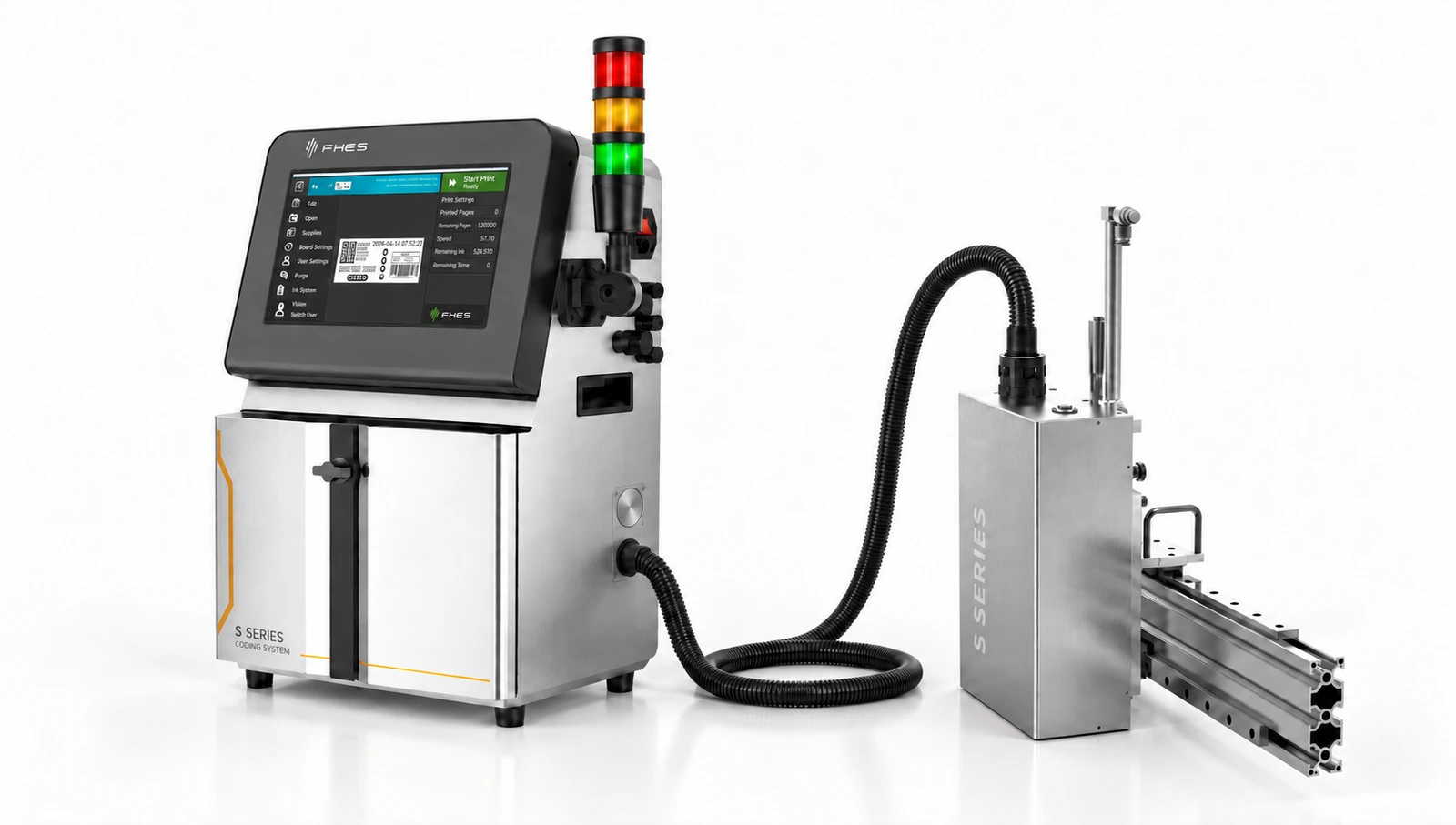
01 / FULL-LOOP CIRCULATION
From the ink tank, through the supply pump and printhead inlet, then through the printhead return path and return pump back to the tank.
Establish ink supply conditions at the printhead inlet.
Observe ink-path status through inlet and return-path pressure feedback.
Return ink to the tank along the return path.
Manage the ink supply/return path from the tank through the printhead and back to the tank, monitoring pressure before and after the printhead during multi-orientation operation.
The recirculation path enters the compatible printhead's internal flow path; the extent of exchange near the nozzles depends on the printhead structure.
Explore CCS ↗System-level full-loop circulation does not automatically mean ink circulates behind the nozzles; confirm the internal printhead flow path and actual circulation coverage for the compatible model.
02 / DUAL PRESSURE FEEDBACK
Pressure before the printhead Pin and return-path pressure Pout provide separate feedback, with dual-pump PID coordinating ink supply/return status and pressure differential.
Monitor ink supply status near the printhead inlet and adjust with the supply pump.
Monitor return-side status and adjust the flow path with the return pump.
When the printhead, tubing or orientation changes, monitor pressure before and after the printhead together with printing status.
Control response varies with pumps, sensors, tubing length, ink and parameter settings; the brochure does not provide a uniform pressure accuracy that can be used directly as an acceptance criterion.
03 / APPLICATIONS
Design ink supply/return configurations for side printing, upward printing and moving platforms according to the workpiece and motion path.
Check pressure changes before and after the printhead against its mounting orientation, ink level and tubing arrangement.
Check hose movement, trigger timing and printing consistency during acceleration, deceleration, turns, stops and starts.
The brochure lists S1–S4 modules and long-throw printing applications; configure according to the specific model.
“360°” is a system design objective stated in the brochure, not a universal guarantee for any orientation. The maximum 50 mm printing distance also depends on the printhead, ink, waveform, speed and substrate, and requires sample validation.
04 / PROJECT VALIDATION
Select the printhead and ink first, then test at the target orientation, motion path and production-line cycle time.
APPLICATION TEST / FHES
Provide the printhead, ink, target orientation, tubing and cycle time to help check dual-pump control and validate on site.